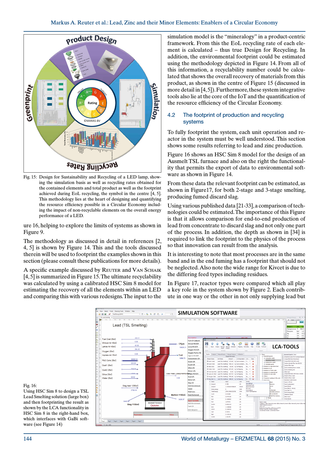
World of Metallurgy ERZMETALL 68 2015 No 3144 Markus A Reuter et al Lead Zinc and their Minor Elements Enablers of a Circular Economy ure 16 helping to explore the limits of systems as shown in Figure 9 The methodology as discussed in detail in references 2 4 5 is shown by Figure 14 This and the tools discussed therein will be used to footprint the examples shown in this section please consult these publications for more details A specific example discussed by reuter and Van Schaik 4 5 is summarized in Figure 15 The ultimate recyclability was calculated by using a calibrated HSC Sim 8 model for estimating the recovery of all the elements within an LED and comparing this with various redesigns The input to the simulation model is the mineralogy in a product centric framework From this the EoL recycling rate of each ele ment is calculated thus true Design for Recycling In addition the environmental footprint could be estimated using the methodology depicted in Figure 14 From all of this information a recyclability number could be calcu lated that shows the overall recovery of materials from this product as shown in the centre of Figure 15 discussed in more detail in 4 5 Furthermore these system integrative tools also lie at the core of the IoT and the quantification of the resource efficiency of the Circular Economy 4 2 The footprint of production and recycling systems To fully footprint the system each unit operation and re actor in the system must be well understood This section shows some results referring to lead and zinc production Figure 16 shows an HSC Sim 8 model for the design of an Ausmelt TSL furnace and also on the right the functional ity that permits the export of data to environmental soft ware as shown in Figure 14 From these data the relevant footprint can be estimated as shown in Figure17 for both 2 stage and 3 stage smelting producing fumed discard slag Using various published data 21 33 a comparison of tech nologies could be estimated The importance of this Figure is that it allows comparison for end to end production of lead from concentrate to discard slag and not only one part of the process In addition the depth as shown in 34 is required to link the footprint to the physics of the process so that innovation can result from the analysis It is interesting to note that most processes are in the same band and in the end fuming has a footprint that should not be neglected Also note the wide range for Kivcet is due to the differing feed types including residues In Figure 17 reactor types were compared which all play a key role in the system shown by Figure 2 Each contrib ute in one way or the other in not only supplying lead but Fig 15 Design for Sustainability and Recycling of a LED lamp show ing the simulation basis as well as recycling rates obtained for the contained elements and total product as well as the footprint achieved during EoL recycling the symbol in the centre 4 5 This methodology lies at the heart of designing and quantifying the resource efficiency possible in a Circular Economy includ ing the impact of non recyclable elements on the overall energy performance of a LED Fig 16 Using HSC Sim 8 to design a TSL Lead Smelting solution large box and then footprinting the result as shown by the LCA functionality in HSC Sim 8 in the right hand box which interfaces with GaBi soft ware see Figure 14 Figure 16 Reuter SIMULATION SOFTWARE LCA TOOLS 0 20 40 60 80 100 A g A l A l2 O 3 A u B aO B a B i C C 5O 2H 8 n C6 H 12 Cl 3O 4P C1 5H 12 B r4 O 2 C 25 H 30 O 4N n C1 2H 12 O 4n Ca O Co C r Cu Fe M g M gO M n N i Pb Pd R u R EE s Si lic on e Si Si O 2 Sn Sr O Ti O 2 Ti V Zn TO TA L R EC O V ER Y To ta l R ec ov er y 38 48 41 46 15 Rating MARAS BV
Hinweis: Dies ist eine maschinenlesbare No-Flash Ansicht.
Klicken Sie hier um zur Online-Version zu gelangen.
Klicken Sie hier um zur Online-Version zu gelangen.