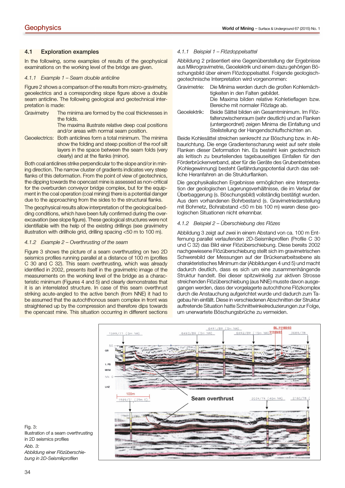
34 World of Mining Surface Underground 67 2015 No 1Geophysics 4 1 Exploration examples in the following some examples of results of the geophysical examinations on the working level of the bridge are given 4 1 1 Example 1 Seam double anticline Figure 2 shows a comparison of the results from micro gravimetry geoelectrics and a corresponding slope figure above a double seam anticline the following geological and geotechnical inter pretation is made Gravimetry the minima are formed by the coal thicknesses in the folds the maxima illustrate relative deep coal positions and or areas with normal seam position Geoelectrics Both anticlines form a total minimum the minima show the folding and steep position of the roof silt layers in the space between the seam folds very clearly and at the flanks minor Both coal anticlines strike perpendicular to the slope and or in min ing direction the narrow cluster of gradients indicates very steep flanks of this deformation From the point of view of geotechnics the dipping towards the opencast mine is assessed as non critical for the overburden conveyor bridge complex but for the equip ment in the coal operation coal mining there is a potential danger due to the approaching from the sides to the structural flanks the geophysical results allow interpretation of the geological bed ding conditions which have been fully confirmed during the over excavation see slope figure these geological structures were not identifiable with the help of the existing drillings see gravimetry illustration with drillhole grid drilling spacing 50 m to 100 m 4 1 2 Example 2 Overthrusting of the seam Figure 3 shows the picture of a seam overthrusting on two 2D seismics profiles running parallel at a distance of 100 m profiles c 30 and c 32 this seam overthrusting which was already identified in 2002 presents itself in the gravimetric image of the measurements on the working level of the bridge as a charac teristic minimum Figures 4 and 5 and clearly demonstrates that it is an interrelated structure in case of this seam overthrust striking acute angled to the active bench from nne it had to be assumed that the autochthonous seam complex in front was straightened up by the compression and therefore dips towards the opencast mine this situation occurring in different sections 4 1 1 Beispiel 1 Flözdoppelsattel abbildung 2 präsentiert eine Gegenüberstellung der ergebnisse aus Mikrogravimetrie Geoelektrik und einem dazu gehörigen Bö schungsbild über einem Flözdoppelsattel Folgende geologisch geotechnische interpretation wird vorgenommen Gravimetrie Die Minima werden durch die großen Kohlemäch tigkeiten in den Falten gebildet Die Maxima bilden relative Kohletieflagen bzw Bereiche mit normaler Flözlage ab Geoelektrik Beide Sättel bilden ein Gesamtminimum im Flöz faltenzwischenraum sehr deutlich und an Flanken untergeordnet zeigen Minima die einfaltung und Steilstellung der Hangendschluffschichten an Beide Kohlesättel streichen senkrecht zur Böschung bzw in ab baurichtung Die enge Gradientenscharung weist auf sehr steile Flanken dieser Deformation hin es besteht kein geotechnisch als kritisch zu beurteilendes tagebauseitiges einfallen für den Förderbrückenverband aber für die Geräte des Grubenbetriebes Kohlegewinnung besteht Gefährdungspotential durch das seit liche Heranfahren an die Strukturflanken Die geophysikalischen ergebnisse ermöglichen eine interpreta tion der geologischen lagerungsverhältnisse die im Verlauf der überbaggerung s Böschungsbild vollständig bestätigt wurden aus dem vorhandenen Bohrbestand s Gravimetriedarstellung mit Bohrnetz Bohrabstand 50 m bis 100 m waren diese geo logischen Situationen nicht erkennbar 4 1 2 Beispiel 2 Überschiebung des Flözes abbildung 3 zeigt auf zwei in einem abstand von ca 100 m ent fernung parallel verlaufenden 2D Seismikprofilen Profile c 30 und c 32 das Bild einer Flözüberschiebung Diese bereits 2002 nachgewiesene Flözüberschiebung stellt sich im gravimetrischen Schwerebild der Messungen auf der Brückenarbeitsebene als charakteristisches Minimum dar abbildungen 4 und 5 und macht dadurch deutlich dass es sich um eine zusammenhängende Struktur handelt Bei dieser spitzwinkelig zur aktiven Strosse streichenden Flözüberschiebung aus nne musste davon ausge gangen werden dass der vorgelagerte autochthone Flözkomplex durch die anstauchung aufgerichtet wurde und dadurch zum ta gebau hin einfällt Diese in verschiedenen abschnitten der Struktur auftretende Situation hatte Schnittwinkelreduzierungen zur Folge um unerwartete Böschungsbrüche zu vermeiden Fig 3 illustration of a seam overthrusting in 2D seismics profiles Abb 3 Abbildung einer Flözüberschie bung in 2D Seismikprofilen
Hinweis: Dies ist eine maschinenlesbare No-Flash Ansicht.
Klicken Sie hier um zur Online-Version zu gelangen.
Klicken Sie hier um zur Online-Version zu gelangen.