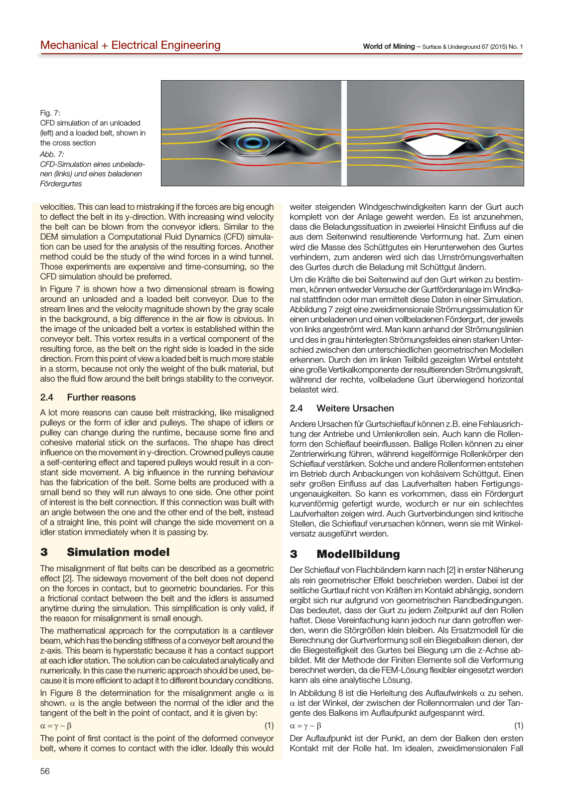
56 World of Mining Surface Underground 67 2015 No 1Mechanical Electrical Engineering weiter steigenden Windgeschwindigkeiten kann der Gurt auch komplett von der Anlage geweht werden Es ist anzunehmen dass die Beladungssituation in zweierlei Hinsicht Einfluss auf die aus dem Seitenwind resultierende Verformung hat Zum einen wird die Masse des Schüttgutes ein Herunterwehen des Gurtes verhindern zum anderen wird sich das Umströmungsverhalten des Gurtes durch die Beladung mit Schüttgut ändern Um die Kräfte die bei Seitenwind auf den Gurt wirken zu bestim men können entweder Versuche der Gurtförderanlage im Windka nal stattfinden oder man ermittelt diese Daten in einer Simulation Abbildung 7 zeigt eine zweidimensionale Strömungssimulation für einen unbeladenen und einen vollbeladenen Fördergurt der jeweils von links angeströmt wird Man kann anhand der Strömungslinien und des in grau hinterlegten Strömungsfeldes einen starken Unter schied zwischen den unterschiedlichen geometrischen Modellen erkennen Durch den im linken Teilbild gezeigten Wirbel entsteht eine große Vertikalkomponente der resultierenden Strömungskraft während der rechte vollbeladene Gurt überwiegend horizontal belastet wird 2 4 Weitere Ursachen Andere Ursachen für Gurtschieflauf können z B eine Fehlausrich tung der Antriebe und Umlenkrollen sein Auch kann die Rollen form den Schieflauf beeinflussen Ballige Rollen können zu einer Zentrierwirkung führen während kegelförmige Rollenkörper den Schieflauf verstärken Solche und andere Rollenformen entstehen im Betrieb durch Anbackungen von kohäsivem Schüttgut Einen sehr großen Einfluss auf das Laufverhalten haben Fertigungs ungenauigkeiten So kann es vorkommen dass ein Fördergurt kurvenförmig gefertigt wurde wodurch er nur ein schlechtes Laufverhalten zeigen wird Auch Gurtverbindungen sind kritische Stellen die Schieflauf verursachen können wenn sie mit Winkel versatz ausgeführt werden 3 Modellbildung Der Schieflauf von Flachbändern kann nach 2 in erster Näherung als rein geometrischer Effekt beschrieben werden Dabei ist der seitliche Gurtlauf nicht von Kräften im Kontakt abhängig sondern ergibt sich nur aufgrund von geometrischen Randbedingungen Das bedeutet dass der Gurt zu jedem Zeitpunkt auf den Rollen haftet Diese Vereinfachung kann jedoch nur dann getroffen wer den wenn die Störgrößen klein bleiben Als Ersatzmodell für die Berechnung der Gurtverformung soll ein Biegebalken dienen der die Biegesteifigkeit des Gurtes bei Biegung um die z Achse ab bildet Mit der Methode der Finiten Elemente soll die Verformung berechnet werden da die FEM Lösung flexibler eingesetzt werden kann als eine analytische Lösung In Abbildung 8 ist die Herleitung des Auflaufwinkels α zu sehen α ist der Winkel der zwischen der Rollennormalen und der Tan gente des Balkens im Auflaufpunkt aufgespannt wird α γ β 1 Der Auflaufpunkt ist der Punkt an dem der Balken den ersten Kontakt mit der Rolle hat Im idealen zweidimensionalen Fall velocities This can lead to mistraking if the forces are big enough to deflect the belt in its y direction With increasing wind velocity the belt can be blown from the conveyor idlers Similar to the DEM simulation a Computational Fluid Dynamics CFD simula tion can be used for the analysis of the resulting forces Another method could be the study of the wind forces in a wind tunnel Those experiments are expensive and time consuming so the CFD simulation should be preferred In Figure 7 is shown how a two dimensional stream is flowing around an unloaded and a loaded belt conveyor Due to the stream lines and the velocity magnitude shown by the gray scale in the background a big difference in the air flow is obvious In the image of the unloaded belt a vortex is established within the conveyor belt This vortex results in a vertical component of the resulting force as the belt on the right side is loaded in the side direction From this point of view a loaded belt is much more stable in a storm because not only the weight of the bulk material but also the fluid flow around the belt brings stability to the conveyor 2 4 Further reasons A lot more reasons can cause belt mistracking like misaligned pulleys or the form of idler and pulleys The shape of idlers or pulley can change during the runtime because some fine and cohesive material stick on the surfaces The shape has direct influence on the movement in y direction Crowned pulleys cause a self centering effect and tapered pulleys would result in a con stant side movement A big influence in the running behaviour has the fabrication of the belt Some belts are produced with a small bend so they will run always to one side One other point of interest is the belt connection If this connection was built with an angle between the one and the other end of the belt instead of a straight line this point will change the side movement on a idler station immediately when it is passing by 3 Simulation model The misalignment of flat belts can be described as a geometric effect 2 The sideways movement of the belt does not depend on the forces in contact but to geometric boundaries For this a frictional contact between the belt and the idlers is assumed anytime during the simulation This simplification is only valid if the reason for misalignment is small enough The mathematical approach for the computation is a cantilever beam which has the bending stiffness of a conveyor belt around the z axis This beam is hyperstatic because it has a contact support at each idler station The solution can be calculated analytically and numerically In this case the numeric approach should be used be cause it is more efficient to adapt it to different boundary conditions In Figure 8 the determination for the misalignment angle α is shown α is the angle between the normal of the idler and the tangent of the belt in the point of contact and it is given by α γ β 1 The point of first contact is the point of the deformed conveyor belt where it comes to contact with the idler Ideally this would Fig 7 CFD simulation of an unloaded left and a loaded belt shown in the cross section Abb 7 CFD Simulation eines unbelade nen links und eines beladenen Fördergurtes
Hinweis: Dies ist eine maschinenlesbare No-Flash Ansicht.
Klicken Sie hier um zur Online-Version zu gelangen.
Klicken Sie hier um zur Online-Version zu gelangen.