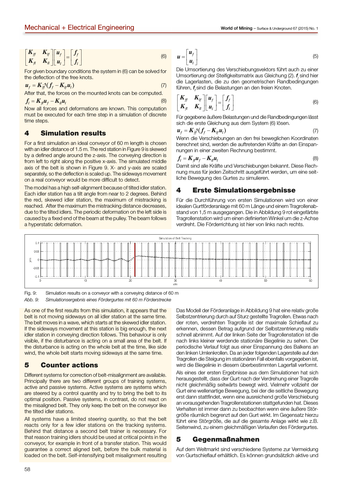
58 World of Mining Surface Underground 67 2015 No 1Mechanical Electrical Engineering f l u u u 5 Die Umsortierung des Verschiebungsvektors führt auch zu einer Umsortierung der Steifigkeitsmatrix aus Gleichung 2 fl sind hier die Lagerlasten die zu den geometrischen Randbedingungen führen ff sind die Belastungen an den freien Knoten ff lf f f fl ll l l K K u f K K u f 6 Für gegebene äußere Belastungen und die Randbedingungen lässt sich die erste Gleichung aus dem System 6 lösen f ff f lf l 1u K f K u 7 Wenn die Verschiebungen an den frei beweglichen Koordinaten berechnet sind werden die auftretenden Kräfte an den Einspan nungen in einer zweiten Rechnung bestimmt l fl f ll l f K u K u 8 Damit sind alle Kräfte und Verschiebungen bekannt Diese Rech nung muss für jeden Zeitschritt ausgeführt werden um eine seit liche Bewegung des Gurtes zu simulieren 4 Erste Simulationsergebnisse Für die Durchführung von ersten Simulationen wird von einer idealen Gurtförderanlage mit 60 m Länge und einem Tragrollenab stand von 1 5 m ausgegangen Die in Abbildung 9 rot eingefärbte Tragrollenstation wird um einen definierten Winkel um die z Achse verdreht Die Förderrichtung ist hier von links nach rechts ff lf f f fl ll l l K K u f K K u f 6 For given boundary conditions the system in 6 can be solved for the deflection of the free knots f ff f lf l 1u K f K u 7 After that the forces on the mounted knots can be computed l fl f ll l f K u K u 8 Now all forces and deformations are known This computation must be executed for each time step in a simulation of discrete time steps 4 Simulation results For a first simulation an ideal conveyor of 60 m length is chosen with an idler distance of 1 5 m The red station in Figure 9 is skewed by a defined angle around the z axis The conveying direction is from left to right along the positive x axis The simulated middle axis of the belt is shown in Figure 9 X and y axis are scaled separately so the deflection is scaled up The sideways movement on a real conveyor would be more difficult to detect The model has a high self alignment because of tilted idler station Each idler station has a tilt angle from near to 2 degrees Behind the red skewed idler station the maximum of mistracking is reached After the maximum the mistracking distance decreases due to the tilted idlers The periodic deformation on the left side is caused by a fixed end of the beam at the pulley The beam follows a hyperstatic deformation As one of the first results from this simulation it appears that the belt is not moving sideways on all idler station at the same time The belt moves in a wave which starts at the skewed idler station If the sideways movement at this station is big enough the next idler station in conveying direction follows This behaviour is only visible if the disturbance is acting on a small area of the belt If the disturbance is acting on the whole belt at the time like side wind the whole belt starts moving sideways at the same time 5 Counter actions Different systems for correction of belt misalignment are available Principally there are two different groups of training systems active and passive systems Active systems are systems which are steered by a control quantity and try to bring the belt to its optimal position Passive systems in contrast do not react on the misaligned belt They only keep the belt on the conveyor like the tilted idler stations All systems have a limited steering quantity so that the belt reacts only for a few idler stations on the tracking systems Behind that distance a second belt trainer is necessary For that reason training idlers should be used at critical points in the conveyor for example in front of a transfer station This would guarantee a correct aligned belt before the bulk material is loaded on the belt Self intensifying belt misalignment resulting Das Modell der Förderanlage in Abbildung 9 hat eine relativ große Selbstzentrierung durch auf Sturz gestellte Tragrollen Etwas nach der roten verdrehten Tragrolle ist der maximale Schieflauf zu erkennen dessen Betrag aufgrund der Selbstzentrierung relativ schnell abnimmt Auf der linken Seite der Tragrollenstation ist die nach links kleiner werdende stationäre Biegelinie zu sehen Der periodische Verlauf folgt aus einer Einspannung des Balkens an den linken Umlenkrollen Da an jeder folgenden Lagerstelle auf den Tragrollen die Steigung im stationären Fall ebenfalls vorgegeben ist wird die Biegelinie in diesem überbestimmten Lagerfall verformt Als eines der ersten Ergebnisse aus dem Simulationen hat sich herausgestellt dass der Gurt nach der Verdrehung einer Tragrolle nicht gleichmäßig seitwärts bewegt wird Vielmehr vollzieht der Gurt eine wellenartige Bewegung bei der die seitliche Bewegung erst dann stattfindet wenn eine ausreichend große Verschiebung an vorausgehenden Tragrollenstationen stattgefunden hat Dieses Verhalten ist immer dann zu beobachten wenn eine äußere Stör größe räumlich begrenzt auf den Gurt wirkt Im Gegensatz hierzu führt eine Störgröße die auf die gesamte Anlage wirkt wie z B Seitenwind zu einem gleichmäßigen Verlaufen des Fördergurtes 5 Gegenmaßnahmen Auf dem Weltmarkt sind verschiedene Systeme zur Vermeidung von Gurtschieflauf erhältlich Es können grundsätzlich aktive und Fig 9 Simulation results on a conveyor with a conveying distance of 60 m Abb 9 Simulationsergebnis eines Fördergurtes mit 60 m Förderstrecke
Hinweis: Dies ist eine maschinenlesbare No-Flash Ansicht.
Klicken Sie hier um zur Online-Version zu gelangen.
Klicken Sie hier um zur Online-Version zu gelangen.